How to Control a Three-Phase Motor Using PLC and VFD
Implementing automated control for industrial motors requires careful planning and execution. In this comprehensive guide, we’ll walk through building a PLC-controlled three-phase motor system with VFD for bidirectional operation.
Project Overview
This industrial automation project enables:
- Smooth motor start/stop sequences
- Safe direction reversal
- Protective interlocks
- Programmable timing functions
All through the combined power of programmable logic controllers (PLC) and variable frequency drives (VFD).

Basic introduction to Power System
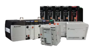
Required Components
To build this system, you’ll need:
Control Components
- PLC unit (Siemens, Allen-Bradley, etc.)
- VFD (2.2kW-5.5kW typical)
- Control relays (24VDC coil)
- Power contactors
Power Components
- Three-phase motor (matched to VFD rating)
- Circuit breakers (main and branch)
- Emergency stop buttons
- Selector switches
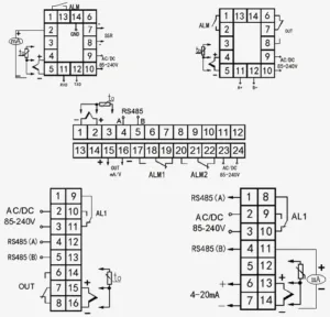
Wiring Essentials
- Control cables (shielded for VFD signals)
- Power cables (proper gauge)
- Terminal blocks
- DIN rail mounting
System Design & Wiring
Control Circuit Architecture
The intelligent backbone comprises:
- Operator inputs → PLC digital inputs
- PLC logic processing → Outputs to relays
- Relay contacts → Command VFD terminals
- VFD power stage → Drives motor
Critical Safety Features
- Electrical isolation between PLC and power circuits
- Physical interlocks on contactors
- Emergency stop hardwired to VFD enable
- Overload protection on all phases
PLC Programming Essentials
The control logic handles:
Motor Commands
NETWORK 1: Forward Run
IF "ForwardPB" AND NOT "ReversePB" THEN
   "ForwardCmd" := TRUE;
END_IF;
Protective Logic
- Direction interlock: Prevents simultaneous FWD/REV
- Start delay timer: 2-sec VFD pre-charge
- Safety cooldown: 5-sec post-stop lockout
VFD Configuration
Key parameter settings:
|
Parameter |
Setting |
Purpose |
|
P0.01 |
1 |
Terminal control |
|
P0.03 |
5Hz |
Start frequency |
|
P0.04 |
50Hz |
Base frequency |
|
P1.04 |
3s |
Acceleration time |
Testing Procedures
Validation Checklist
- Verify proper motor rotation direction
- Confirm forward/reverse interlocking
- Test emergency stop functionality
- Validate overload protection
- Check alarm conditions
Common Troubleshooting Tips
Motor Not Starting
- Check 24V control power
- Verify PLC outputs energizing
- Inspect VFD run command LED
Unexpected Direction Changes
- Validate wiring sequence (U-V-W)
- Check for crossed control wires
- Confirm interlock logic in program
Advanced Enhancements
Take your project further with:
- Modbus RTU communication between PLC-VFD
- Analog speed control via 0-10V input
- PID regulation for process control
- HMI integration for operator visualization
Final Thoughts
This PLC/VFD motor control solution delivers:
✅ Precise speed regulation
✅ Safe bidirectional operation
✅ Programmable automation
✅ Industrial reliability
For complex implementations, always consult local electrical codes and consider working with certified automation professionals.