Prerequisites: Preparing for a Smooth I/O Card Addition
Before adding an I/O card to your existing Point I/O rack, taking time to prepare is key to avoiding headaches down the road. Here’s what to check first:
Assess your current setup:
- Rack capacity – Confirm there’s space for another module without overcrowding.
- Firmware versions – Make sure the new I/O card’s firmware matches or is compatible with your existing Point I/O rack firmware.
- Network protocol – Verify your communication system (EtherNet/IP, DeviceNet, ControlNet) supports the added module without configuration conflicts.
Gather essential tools and materials:
- Allen-Bradley Point I/O module (correct 1734 series part)
- Terminal blocks and wiring tools (stripper, screwdrivers)
- PC with Studio 5000 software or RSLogix 5000 for configuration
- Safety gear like gloves and eye protection
Safety and compatibility checklist:
- Confirm power is off before touching hardware
- Check electrical ratings and compatibility with the existing system
- Follow grounding and wiring standards for industrial automation
Pro tip: Run a pre-installation audit
- Document your current rack layout and module slots
- Back up your current PLC project files
- Double-check compatibility to save time during installation
Taking these steps upfront creates a smooth path for your Allen-Bradley Point I/O expansion and avoids common pitfalls like firmware clashes or network hiccups. Let’s get ready to physically add that new I/O card!
Hardware Installation: Physically Adding the I/O Card
Before you start, make sure the Point I/O rack is powered down to avoid any electrical hazards. Disconnect power at the main breaker or control panel, then unlock and open the rack door for easy access.
When adding the I/O card, pay attention to wiring best practices:
- Terminal connections: Use the correct wire gauge for each terminal and ensure each wire is securely fastened.
- Label everything: Clearly label each wire and terminal to avoid confusion during troubleshooting or future expansions.
- Grounding: Properly ground the card and the rack chassis according to Allen-Bradley’s specs to minimize electrical noise and improve system reliability.
If you’re inserting the new card in the middle of the rack, you might need to temporarily shift existing modules to create space. Keep an eye on slot indexing—each module position matters for communication and addressing. For longer distances or awkward layouts, extension cables can help maintain neatness without compromising signal integrity.
A good tip is to refer to Allen-Bradley’s slot layout diagrams during installation. These visuals clearly show you where each module sits, how to mount it, and where the terminals line up. Having photos or marked guides handy makes installation quicker and reduces mistakes, especially when working on a live industrial automation setup.
Following these steps ensures your Point I/O hardware setup is solid, ready for the next step—software configuration.
Software Configuration: Integrating the New Card in Studio 5000
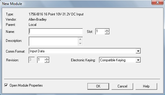
Once the I/O card is physically installed, it’s time to set it up in Studio 5000. Start by opening your project and navigating to the I/O Configuration tree. Here, you’ll add a new module for the card you just installed.
Key steps include:
- Module selection: Choose the exact Point I/O module type that matches your hardware.
- Slot assignment: Assign the new card to the correct slot number in the rack. This ensures the controller recognizes it properly.
- Chassis size adjustment: If your rack size has changed due to the added card, update the chassis size in the software to avoid addressing issues later.
You can configure this either online (while connected and running) or offline (before uploading to the controller). Online programming lets you see live statuses and minimize downtime, but offline changes are safer for big setup revisions.
After adding the module, create and map new tags for its inputs and outputs. If you have aliased tags from older modules, don’t forget to re-index them to match the new configuration. This keeps your PLC logic clean and accurate.
Pro tip: If you’re linking the Point I/O to a CNC controller, use simple ladder logic snippets for your input/output mapping. This helps ensure smooth communication and easy troubleshooting down the line.
Following these steps makes your Allen-Bradley Point I/O expansion fast and reliable, keeping your automation running without a hitch.
Network and Communication Setup: Ensuring Seamless Connectivity
When adding an I/O card to your existing Point I/O rack, network setup is key for smooth communication. Start with IP addressing—using BOOTP (Bootstrap Protocol) is the easiest way to assign IP addresses to your new modules without manual input. This helps your Allen-Bradley Point I/O expansion slot right into your EtherNet/IP network.
Next, check your rack-optimization settings. Adjusting the chassis size and slot assignments in Studio 5000 not only improves performance but also reduces network traffic delays. This keeps your data flowing smoothly between the PLC and the new I/O module.
If you’re working with fieldbus systems like DeviceNet or ControlNet, follow these quick steps:
- Connect the fieldbus cable properly to the new module.
- Configure the device address to avoid conflicts.
- Use RSNetWorx or similar tools to integrate the new module into the existing network.
- Double-check wiring and terminators for a clean bus.
Common network faults often come from incorrect IPs, cable problems, or firmware mismatches. If your new card isn’t showing up, verify IP settings with BOOTP, check cable connections, and confirm firmware compatibility using Rockwell’s guidelines.
Making sure your new I/O card communicates well means less downtime and a more reliable automation system. With the right setup, your Point I/O rack expands without headaches.
Testing and Verification: Confirming Operational Integrity
Once your Point I/O card is installed and configured, it’s crucial to verify everything works as expected before going live.
Power-Up Sequence and Fault LEDs
- Power up the rack and watch the status LEDs on the new I/O card closely.
- Green LEDs usually mean normal operation, while amber or red often signal faults.
- Check the rack’s overall health indicators for any warnings related to your new module.
Functional Testing
- Use your PLC or Studio 5000 to simulate I/O signals, ensuring inputs and outputs respond correctly.
- Validate tags associated with the new card to confirm they’re reading and writing as intended.
- Trigger physical devices where possible to confirm real-world responses.
Performance Benchmarks
- Monitor for any changes in latency or scan times after adding the card, especially in production-critical applications.
- Ensure that the additional module doesn’t negatively impact overall rack communication or PLC cycle time.
Validation Tools
- Utilize downloadable post-installation checklists tailored for Allen-Bradley Point I/O expansions to make sure nothing gets missed.
- These tools help cross-check wiring, configuration, and firmware alignment for a smooth operation.
Following this testing and verification step gives you confidence your Point I/O card addition is solid and ready for production.
Common Challenges and Troubleshooting: Real-World Fixes

Adding an I/O card to your existing Point I/O rack isn’t always smooth sailing. Here are some common issues and how to fix them:
- Tag shifts and reordering: When you insert a new card, tag addresses can shift, messing up your logic. The fix? Use the PLC rack tag re-indexing feature in Studio 5000 to reorder tags quickly and keep everything mapped correctly.
- Firmware mismatches: Different firmware versions between the new I/O card and your existing rack components can cause communication glitches. Always check Rockwell firmware compatibility before installation. If needed, update your modules through the Studio 5000 Device Update tool.
- RUN-mode limitations: You often can’t add new modules while the PLC is running. If running online, switch to a safe state or use offline configuration to add and configure the new card, then download changes during scheduled downtime.
- Advanced pitfalls: Watch out for incorrect slot assignment or chassis size adjustments—it’s common to forget updating these in software, which breaks communication. Double-check your setup before going live.
- Diagnostic tips: Use the built-in diagnostics in Studio 5000 to monitor fault LEDs, communication status, and I/O responses. Early detection saves troubleshooting time.
Case study: In a recent online rack expansion, the operator avoided downtime by first completing an offline configuration. After verifying slot and module settings, they successfully downloaded updates during a scheduled break. No faults or tag errors appeared, highlighting the importance of planning and diagnostics.
Remember, a careful approach to common problems ensures your Allen-Bradley Point I/O expansion goes smoothly every time. For advanced module needs, explore compatible Omron I/O units that can integrate seamlessly in mixed environments.
Best Practices for Long-Term Point I/O Management
To keep your Point I/O system running smoothly over time, planning for scalability and easy maintenance is key. Here’s how to manage it effectively:
Scalability Strategies and Modular Layouts
- Design with growth in mind: Use modular rack setups that let you add or swap I/O cards without big overhauls.
- Keep spare slots open: Always leave a few empty slots in the rack for future expansion.
- Group related modules: Organize modules by function or process area for easier troubleshooting and upgrades.
Maintenance Routines and Spare Parts Management
- Schedule regular checks: Inspect connectors, wiring, and module LEDs to catch issues early.
- Track firmware versions: Keep Rockwell firmware and Studio 5000 software up to date for compatibility.
- Stock critical spares: Maintain an inventory of commonly replaced cards, cables, and power supplies to reduce downtime.
Optimization Tips for Safety and Space Savings
- Label everything clearly: Use consistent terminal and tag labels to avoid wiring mistakes during expansion.
- Practice neat wiring: Route cables cleanly to improve airflow and reduce damage risk.
- Use proper grounding: Ground the rack and modules as per Allen-Bradley guidelines to prevent electrical noise and protect your system.
Sustainability Benefits of Efficient Expansions
- Minimize material waste: Adding only the needed I/O modules reduces unnecessary hardware use.
- Energy efficiency: Upgrading to newer Point I/O modules can cut power consumption.
- Extend equipment life: Regular firmware updates and proper maintenance help avoid premature hardware replacement.
By following these best practices, your Point I/O expansion will not just fit your current needs but stay reliable, safe, and ready for whatever comes next.