How Rotary Encoders Work
Ever wonder how a CNC machine knows exactly where the tool is positioned down to the micron? It all comes down to the Rotary Encoder. As a specialist manufacturer in motion control, I see these devices as the nervous system of industrial automation. They translate physical mechanical motion into electrical signals that your controller can actually understand.
At the core of our Optical Encoders, the mechanism relies on a precise interplay of three main components:
- Light Source: A focused LED beam provides a constant stream of light.
- Code Disc: This is the heart of the sensor. It is a rotating disc (often glass or metal) etched with precise lines or slits. As the shaft turns, this disc spins, chopping the light beam into intermittent pulses.
- Photo-Detector Array: Sitting on the other side of the disc, these sensors detect the alternating light and dark patterns.
This interaction generates Square Waves. In a standard setup, the detector converts the light pulses into electrical signals, typically outputting Quadrature Output (Phase A and Phase B). By reading these on-off pulses, your PLC or drive system can instantly calculate speed, direction, and relative position. Whether it is a heavy-duty Rotary Position Sensor for an elevator or a high-precision unit for robotics, the fundamental principle remains the reliable conversion of rotation into digital data.
Optical vs. Magnetic Sensing
When selecting a Rotary Encoder, the decision often comes down to the internal sensing mechanism. We generally categorize these into two main technologies: optical and magnetic. Your choice depends entirely on the trade-off between extreme precision and environmental resilience.
Optical Encoders are the standard for high-precision motion control. They utilize a light source, a marked code disc, and a photodetector to generate signals. This design allows for incredibly high resolution and accuracy. If you are outfitting a precision Fanuc servo motor for a CNC application, an optical unit is typically the best fit. They provide superior interference immunity against magnetic fields, but they do require a relatively clean environment since dust or oil can obstruct the optical path.
Magnetic Encoders, on the other hand, are built for the grind. These sensors use magnetic fields and Hall effect technology to track rotation. Because they don’t rely on line-of-sight optics, they are rugged and resistant to dirt, grease, moisture, and heavy vibration. While a magnetic Rotary Position Sensor might not always match the ultra-high resolution of an optical version, it is often the more reliable choice for heavy-duty Industrial Automation Components operating in harsh, dirty conditions.
Key Comparison:
- Optical: Best for high resolution, fast response, and magnetic field immunity. Ideal for clean manufacturing.
- Magnetic: Best for shock resistance, durability, and harsh environments (dust/oil/water). Ideal for heavy machinery.
Incremental vs. Absolute Encoder
Selecting the right sensor for your automation setup usually comes down to the battle of Incremental vs. Absolute Encoder technology. We guide customers through this decision daily, as the choice dictates how your machine handles positioning data and power interruptions. While both types track rotation, they serve fundamentally different roles in industrial motion control.
Here is the breakdown of how these distinct technologies function:
- Incremental Encoders: These are the industry standard for speed and relative distance monitoring. They output a stream of pulses as the shaft turns, often utilizing a Zero Reference Pulse (Z-phase) to mark a home position. The main trade-off is memory; if the power goes out, the encoder “forgets” its location, requiring the machine to perform a homing sequence upon restart.
- Absolute Encoders: Essential for complex applications, these devices assign a unique digital signature—often using Gray Code or binary—to every specific angle of the shaft. This allows the sensor to retain its exact position even after a total power loss. This capability is critical for a high-precision CNC Feedback System or multi-axis robotic arm where re-homing is dangerous or time-consuming.
Whether you require a single-turn absolute model for a robotic joint or a standard incremental unit for a conveyor belt, we provide solutions that integrate seamlessly with the major international manufacturers listed on our comprehensive brand listing.
Matching Specs to Application: PPR, Voltage, and Output
When I help customers select the right Rotary Encoder, we start by looking at the resolution, specifically the Pulses Per Revolution (PPR). This number defines how many square wave pulses the device generates in one full 360-degree turn. It is a balancing act; while a high PPR offers tighter precision for CNC machining, it requires a controller capable of handling high-frequency inputs. For simple speed monitoring on a conveyor belt, a standard resolution is often more than enough and easier to manage.
Next, we have to match the voltage and output logic to your specific control environment. Getting this wrong is the most common reason for installation failure.
- Voltage Requirements: Most of our encoders run on DC 5V or a wider range of DC 8-30V. You need to check your receiving device—connecting a 5V encoder to a 24V industrial source will damage the unit instantly.
- TTL (Line Driver): This is the go-to for high-noise environments or long cable runs. It uses differential signals (A, A-, B, B-) to cancel out electrical interference.
- HTL (Push-Pull): We typically recommend this for standard industrial automation where the encoder connects directly to a 24V interface.
- Open Collector: Ideal if your encoder and controller operate at different voltage potentials.
If you are integrating feedback into a complex automation system, such as wiring inputs to a Siemens S7-1200 PLC, verifying that the encoder’s output type (NPN or PNP) matches the PLC’s input module is critical for reliable signal detection. We offer phases A, B, and Z (zero reference) across these models to ensure compatibility with virtually any counter or drive.
Electrical Interface Selection
Selecting the correct electrical output for your Rotary Encoder is just as important as the mechanical fitment. If the output signal doesn’t match your controller’s input requirements, you will face signal loss, missed counts, or potential hardware damage. We offer several output circuit types to match specific automation environments, primarily distinguishing between high-noise immunity and voltage flexibility.
Line Driver Output (TTL)
For applications requiring long cable runs or operating in electrically noisy environments, the Line Driver Output is the industry standard. This interface uses a differential signal (channels A, A-, B, B-, Z, Z-), which effectively cancels out interference.
- Best for: Servo drives and CNC systems (like Fanuc or Mitsubishi).
- Voltage: Typically 5V DC.
- Benefit: High frequency response and stable transmission over long distances (often exceeding 100 meters).
Open Collector Interface (NPN/PNP)
If you are integrating directly with a Programmable Logic Controller (PLC) or a counter module, the Open Collector Interface is often the required standard. This configuration acts like a switch and usually requires an external pull-up resistor. It is highly compatible with wide voltage ranges (DC 5-30V), making it versatile for various control cabinets.
- Best for: General automation and PLC Interface connections.
- Voltage: Wide range (DC 8-30V is common).
- Benefit: Cost-effective and simple to wire for standard I/O modules, such as the Siemens SIMATIC ET 200SP BaseUnit, ensuring reliable pulse counting without complex signal conditioning.
Push-Pull (HTL)
For a middle-ground solution, our Push-Pull output offers a balance. It provides stable logic levels (High/Low) based on the supply voltage and can often replace Open Collector types in modern systems where sourcing and sinking current is needed. Always verify your controller’s input manual before finalizing the spec.
Mechanical Form Factor: Solid vs. Hollow Shaft Selection
Getting the physical fit right is just as crucial as matching the electrical specs. When you are selecting a Rotary Encoder for your setup, the first decision usually lands on the shaft style. We see two main configurations in the field, and choosing the wrong one can lead to installation headaches or premature failure.
- Solid Shaft Encoders: These are the traditional choice for general automation. They require a separate flexible coupling to connect to the motor or machine shaft. The coupling is vital because it absorbs slight misalignments and protects the encoder bearings from mechanical stress. If you are dealing with heavy vibration, a solid shaft with a robust mounting bracket is often the way to go.
- Hollow Shaft Encoders: Also known as through-hole or blind hollow shafts, these mount directly onto the motor shaft. They are massive space-savers since you don’t need an external coupling or extra bracketry. This design is standard for motor feedback and tight spaces inside CNC Machinery Parts.
We stock a wide range of outer diameters, from compact 38mm units to heavy-duty 100mm industrial sizes. Whether you need a standard 6mm shaft or a custom bore size for a specific motor, we can tailor the Industrial Automation Components to fit your hardware. Always double-check your shaft diameter and mounting bolt pattern before ordering to ensure a drop-in replacement.
Manual Pulse Generator (MPG) for CNC Control
We often treat the Manual Pulse Generator (MPG) as a simple accessory, but it is actually a specialized rotary encoder designed specifically for human input. Unlike the high-speed encoders mounted on motors, this handwheel provides operators with precise, tactile control over CNC machine axes. When you turn the dial, you feel a distinct “click” or detent; this physical feedback is crucial for manual positioning, allowing machinists to zero tools or set up workpieces with micron-level accuracy without overshooting.
For an MPG to function correctly, it must match the electrical specifications of your control system. We offer units compatible with major industrial standards, ensuring seamless integration whether you are connecting to a Fanuc interface or a Siemens PLC system.
Key MPG Specifications:
- Resolution: Typically 100 PPR (Pulses Per Revolution) or 25 PPR, matched to the controller’s gearing.
- Voltage Options: Available in DC 5V, 12V, or 24V to suit different input cards.
- Output Types: Voltage or Differential Line Driver outputs to prevent signal loss over coiled cables.
- Durability: Built to withstand oil, dust, and constant handling in harsh shop environments.
Installation and Troubleshooting
Getting the best performance out of a Rotary Encoder usually comes down to two things: clean wiring and precise mechanical mounting. We see it all the time—perfectly good sensors get blamed for issues that are actually caused by electrical noise or physical misalignment. When you are setting up your automation system, treating the signal path with care is critical.
Wiring and Noise Protection
Electrical noise (EMI) is the enemy of accurate feedback. If your controller counts pulses when the motor isn’t moving, you are likely dealing with “ghost pulses” caused by interference. To prevent this, always use shielded twisted pair cables. The shield needs to be grounded properly—typically at the receiver end (the drive or PLC side) rather than the encoder end—to drain away interference effectively.
When connecting your encoder to the control system, ensure your wiring follows the specific color code for the A, B, and Z phases. This process requires the same attention to detail as a standard I/O card installation to ensure signals are read correctly without bounce or lag.
Mechanical Alignment
Physical stress kills encoders faster than anything else. Whether you are using a solid shaft or a hollow shaft model, never force the unit into place.
- Solid Shaft: Always use a flexible coupling between the encoder shaft and the motor shaft. This absorbs slight misalignments and prevents load from destroying the internal bearings.
- Hollow Shaft: Ensure the spring plate (tether) is secured without tension. If the shaft wobbles, it will wear out the optical disc or magnetic sensor inside.
Common Troubleshooting Tips
If your system isn’t behaving, run through this quick checklist before replacing the unit:
- Drifting Position: Check if the coupling is loose or slipping on the shaft.
- Erratic Counting: Verify the shield ground is secure and not creating a ground loop.
- No Signal: Confirm the power supply voltage matches the encoder spec (e.g., don’t feed 24V into a 5V TTL line driver).
Brand Compatibility and Replacement Encoders
In the fast-paced world of Industrial Automation Components, machine downtime is the enemy. When a critical sensor fails on your production line, waiting weeks for an original equipment manufacturer (OEM) part isn’t just inconvenient—it kills profitability. We understand that urgency. That is why we specialize in manufacturing Rotary Encoders designed as direct, drop-in replacements for major international systems.
We engineer our sensors to match the precise electrical and mechanical specifications of industry giants. Whether you need a Fanuc Compatible unit for a lathe or a replacement for a Mitsubishi servo motor, we provide solutions that get you back up and running immediately. You get the same resolution, the same output signals, and the same durability without the heavy brand-name markup or extended lead times.
Why choose our compatible replacements?
- Seamless Integration: Our encoders match the shaft size, mounting bolt pattern, and wiring pinouts of standard CNC Machinery Parts.
- Reduced Downtime: We stock common configurations to bypass global supply chain delays.
- System Support: Beyond just encoders, we function as a reliable Siemens breakers supplier to ensure your entire control cabinet remains operational.
By switching to high-quality compatible alternatives, you maintain the precision of your CNC equipment while taking control of your maintenance schedule.
Rotary Encoder FAQs
We encounter a lot of specific questions from engineers and maintenance crews trying to keep their lines running. Whether you are dealing with a CNC Feedback System or a simple conveyor setup, getting the details right matters. Here are the answers to the most common technical inquiries we receive about Rotary Encoders.
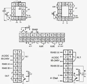
How do I read the wiring diagram correctly?
Never assume color codes are universal. While we stick to industrial standards, the color coding for A, B, and Z phases can vary between manufacturers. Always refer to the label on the encoder body or the datasheet provided.
- Power (Vcc & 0V): Double-check your voltage. Connecting 24V to a 5V Line Driver Output will damage the unit immediately.
- Signal Wires: Ensure your Phase A and Phase B are connected to the correct high-speed counter inputs.
- Shielding: The drain wire must be connected to the ground specifically at the receiver end (PLC or Drive) to drain noise effectively.
- Integration: When wiring an encoder into a complex control cabinet, such as connecting to a Fanuc I/O unit, verify that the input module supports the encoder’s output type (NPN, PNP, or Differential).
Why is my encoder signal drifting or showing “ghost” pulses?
This is almost always signal interference or EMI (Electromagnetic Interference). In a busy shop floor with VFDs and heavy motors, electrical noise can induce false counts.
- Cable Routing: Never run encoder cables in the same conduit as high-voltage power lines.
- Cable Type: We recommend using twisted-pair shielded cables.
- Grounding: Improper grounding creates ground loops. Ensure the machine frame and the encoder body share a common potential.
How do I choose the right Resolution (PPR)?
Higher isn’t always better. Choosing the right Pulses Per Revolution (PPR) depends on your required accuracy and the maximum speed of the application.
- Calculate Frequency: Formula: $(RPM times PPR) / 60 = Frequency (Hz)$.
- Check Limits: Ensure the resulting frequency does not exceed the maximum response frequency of your PLC Interface or counter card.
- Application: For precise positioning on a CNC, high PPR is necessary. For simple speed monitoring, a lower resolution is often more stable and cost-effective.
Can I replace a specific brand with your encoder?
Yes. We specialize in OEM/ODM solutions and can match the mechanical and electrical specifications of major international brands. If you need to replace a faulty encoder on a Mitsubishi servo motor or a Siemens motor, we can configure the shaft size (solid or hollow), flange style, and output logic (TTL/HTL) to provide a direct drop-in replacement. This minimizes downtime without the lead times often associated with big-name OEM parts.